

14
May
AUSTIN’S AIRTH GATES
- By Lefteris Virirakis
A project proposal by Danae Stratou
Analysis and software development by A+V
A FORMAL GEOMETRIC DESCRIPTION
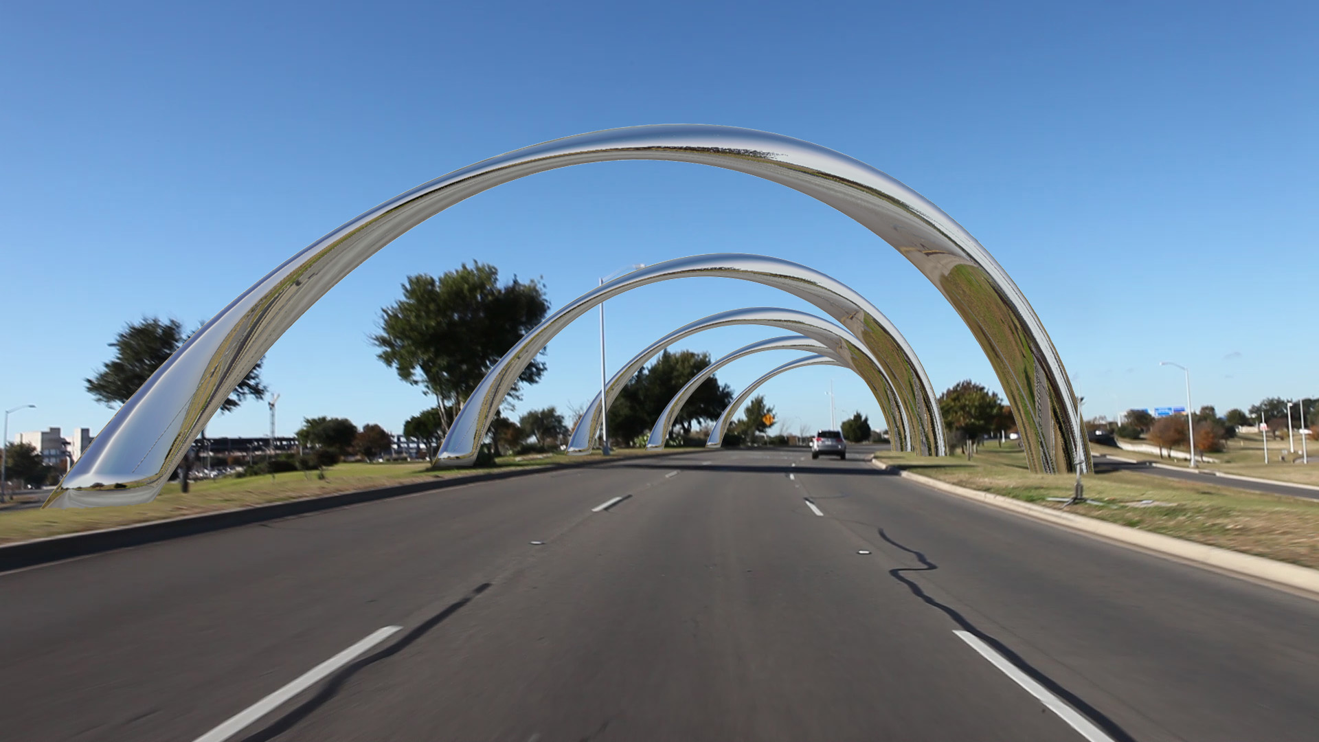
We present a formal geometric description of Danae’s project Austin’s Airth Gates. As the software support team, we had a continuous cooperation with Danae during the project development. Danae explained thoroughly the geometric properties of the project, as well as the control she wished to have on them. After performing the algorithmic analysis, we developed software making possible the parametric definition of the desired properties. Danae worked extensively on the parameters’ values configuration, finally achieving the desired form.
The basic geometric idea is a repeatable Arc-construction standing over a right-turning road. The Arc-construction is defined by a closed 2D shape, referred to as the “cross-section”, sweeping a 3D curve, referred to as the “path”. The “cross-section” is geometrically transformed as it sweeps the “path”. It is required a form of repeatability that alludes a unified continuous construction, a (virtual) part of which is underground.
Now we are going to explain step by step the parametric definition.
The Path
The basic form of the “path” is an elliptical arc drawn on a vertical level. Consider a XYZ coordinate system, referred to as PCS (Path Coordinate System), where the XY level represents the ground, while the Y axis shows the direction of the road. The locus of the “path” is defined on the XZ level as (Xmax×cos(a), 0, Zmax×sin(a)), 0 ≤ a ≤ PI, where Xmax and Zmax are parameters representing the half-lengths of the ellipse’s axes (Shape 1-a).
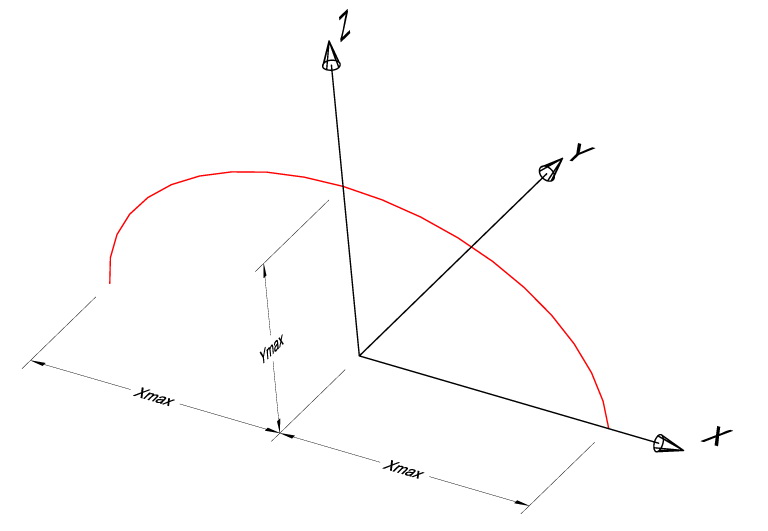
Shape 1-a
The path as an elliptical arc drawn on the XZ level of the PCS.
Now we are going to convert the elliptical arc to an elliptical helix, by introducing the parameter HW (Helix Width). Then the locus becomes:
(Xmax×cos(a), HW (1-a/PI), Zmax×sin(a)), 0 ≤ a ≤ PI (Shape 1-b).
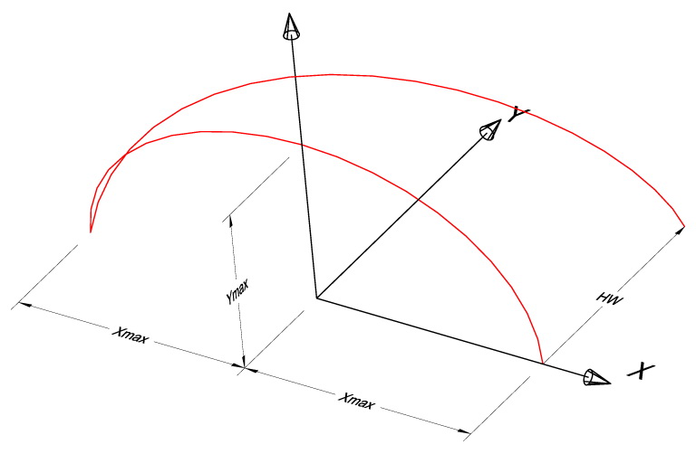
Shape 1-b
Application of the helix transformation, with the introduction the HW parameter
A third step is to introduce a parametric “inclination” of the path, defined as a height-depended deviation towards the Y axis. If INC is the inclination parameter, then the locus becomes:
(Xmax×cos(a), HW×(1-a/PI)+INC×Zmax×sin(a), Zmax×sin(a)), 0 ≤ a ≤ PI (Shape 1-c).
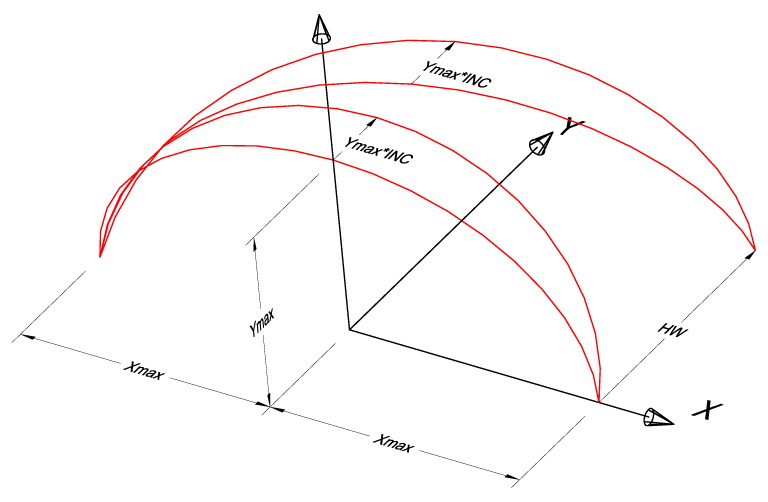
Shape 1-c
Both the initial path (elliptical arc) and the helix-path subjected to the inclination transformation with coefficient INC.
The “path” definition given so far would be fine for a straight road. However, the road is actually curved (turning to the right). Let R be the radius of the curve. We have to apply a “curvature transformation” to the “path”. This can be done by transforming the Cartesian coordinates (x, y) of each (x, y, z) point of the “path’s” locus to polar coordinates having as center the center of the road’s curve, angle y/R counted clockwise from the -X direction in radians, and polar radius R-x (the distance of the x coordinate from the center). The transformed Cartesian coordinates (x’, y’) are given from the equations: x’ = R-(R-x)×cos(y/R), y’ = (R-x) sin(y/R) (Shape 2), while the z coordinate remains intact: z’ = z.
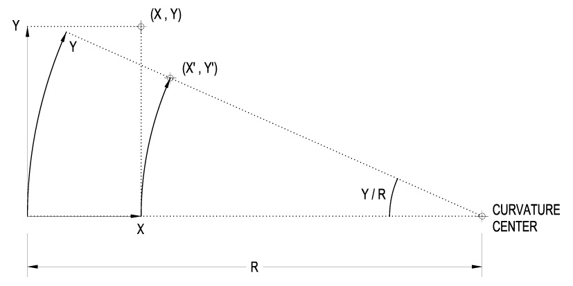
Shape 2
The “curvature transformation”. The point (X, Y) is transformed to the point (X’, Y’). Consider the “curved” Y coordinate: this is an arc centered at the “curvature center”, having radius R and length Y: this arc has angle Y/R (radians). The projection of (X, Y) on the X axis, i.e. the point (X, 0), is rotated by the arc’s angle clockwise around the “curvature center”. The rotation results in the point (X’, Y’).
The Cross-section
Considering the “cross-section” we have to answer three questions:
- a) how its shape is defined
- b) how is it placed with respect to the “path” during the sweeping action
- c) how is it transformed during the sweeping action
The answers are here:
a) The basic shape of the “cross-section” is a full ellipse defined in a local coordinate system, referred to as CCS (Cross‑section Coordinate System). The ellipse’s locus is defined on the XY level of CCS by (cx×cos(a*), cy×sin(a*)), 0 ≤a* < 2×PI, where cx and cy are parameters representing the half-lengths of the ellipse’s axes. However we would like to submit the ellipse to an egg-like deformation by making it relatively thicker / thinner either to the right (positive x portion) or to the left (negative x portion). We achieve this by multiplying the ellipse’s y dimension by 1+c×cos(a*), where c is the egg-deformation parameter: positive values (preferably not bigger than 5) result in a right-thick egg, while negative positive values (preferably not smaller than -0.5) result in a left-thick egg. A 0 value has no effect on the original ellipse (Shape 3).
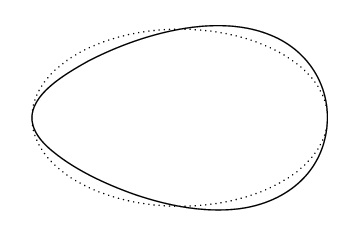
Shape 3
Application of the “egg” deformation to an ellipse: the ellipse (dotted line) has been deformed to a right-thick “egg” by a 0.3 deformation factor (continuous line).
b) This question is reduced to how CCS is placed at each point of the “path”. If we consider the “path” before the “curvature transformation” then the CCS axes’ origin (0, 0) is placed on the “path”, say at point P*, while its X (respectively Y) axis is perpendicular (respectively parallel) to the PCS Y axis. Then we have to apply the “curvature transformation”. First we set the origin of the transformed CCS at the image, name it P, of P*. Then we consider the image, name it Py, of the PCS Y coordinate of P* and we set the (transformed) CCS X axis to point at Py. Finally we set the (transformed) CCS Y axis to be parallel to the tangent at Py to the circle that constitutes image of the PCS Y axis (Shape 4).
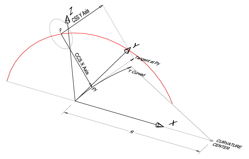
Shape 4
Setting the CCS at a specific position P on a curved helix-shaped path. Consider P as the image—with respect to the “curvature transformation”—of a point (not appearing in the Shape), name it P*, of the un-curved “path”. CCS X axis points at Py (the image of the PCS Y coordinate of P*) while CCS Y axis is parallel to the tangent to the curved PCS Y axis at Py.
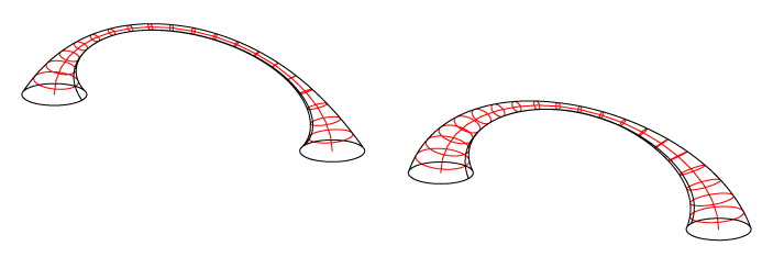
c) Both axes of the elliptical “cross-section” can change size during the sweeping action. The start size, name it S, as well as the end size, name it E, of an axis constitute parameters. By convention, the start-point (respectively the end-point) of the “path” is the point specified by setting a = PI (respectively a = 0) in the “path’s” definition. Alternatively, S could be the size of an axis in both the start-point and the end-point of the “path”, while E the size of the same axis at the mid-point of the “path” (specified by setting a = PI/2). The rate of the size change from S to E during the sweeping action can be controlled by a positive parameter c: the change is linear with a if c = 1, biased to S if c < 1 and biased to E if c > 1. Specifically, we define the axis size at the “path”-point specified by a = PI×(1 – p), 0 ≤ p ≤ 1, to be E + (S ‑ E)×(1 ‑ p)^c if E is associated to the “path’s” end-point, while E + (S ‑ E)×(|1 ‑ 2×p|)^c if E is associated to the “path’s” mid-point (Shape 5).
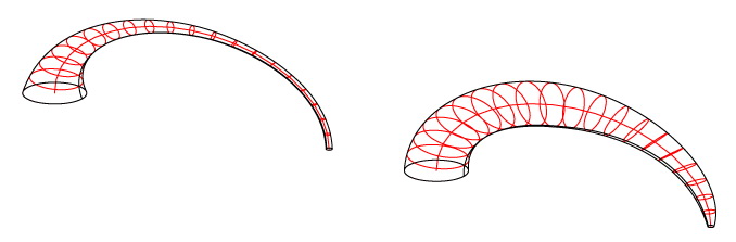
Shape 5-a
Controlling the size-change-rate of the “cross-section” as it sweeps the “path”. In both examples the start-point (respectively the end-point) “cross-section” is a circle having diameter 2 (respectively 0.2). In the left-hand example the size-change-rate parameter has been set to 4, causing a rapid size change (geometry is biased to the end-point “cross-section” size), while in the right-hand example the size-change-rate parameter has been set to 0.7, causing a slow size change (geometry is biased to the start-point “cross-section” size).
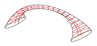
Shape 5-b
The start-point, as well as the end-point “cross-section” is a circle having diameter 2, while the mid-point “cross-section” is a circle having diameter 0.2 in both examples. The size-change-rate parameter has been set to 4 in the left-hand example, while to 2 in the right-hand example.
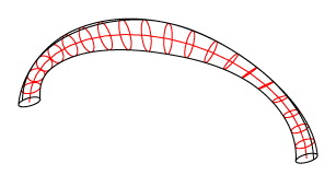
Shape 5-c
Here, the size of each characteristic “cross-section” has been treated differently. In both the start-point and the end-point (respectively the mid-point) “cross-section” the (cx, cy) parameter vector, which specifies the half-lengths of the ellipse’s axes, has been set to (0.5, 2.5) (respectively (0.1, 0.25)).
An additional possibility is to rotate the “cross-section” around the CCS Z axis, as it sweeps the “path”: the rotation angles both at the start-point and the end-point of the “path” constitute parameters. Intermediate rotation angles are specified by linear interpolation with respect to a (Shape 6).
Shape 6
An elliptical (non-egged) “cross-section” subjected to a PI rotation as it sweeps the “path”.
Note that not only the axes’ half-lengths but also any “cross-section” parameter, such as the rotation angle or the egg deformation, could be controlled by an exponential bias. However this was not required for the specific project.
Repeatability
An Arc-construction having a non-zero HW (Helix Width) can be considered as a part of a full Helix-construction whose other overground parts—on a straight road—can be obtained by repeating the initial part by a 2×HW step towards the PCS Y axis. Considering the “curvature transformation”, repetition should be rotational around the center of the curvature by a 2×HW/R angular step counted clockwise in radians. The underground parts can be obtained by inversing both the Y and the Z coordinates of each overground item in its own PCS. Surface continuity between the overground and the underground parts requires some precautions: for instance, continuity can be achieved if the difference of the end-point from the start-point “cross-section’s” rotation angle is a multiple of PI (or even PI/2 if the cross-section is a non-egged ellipse) (Shape 7).
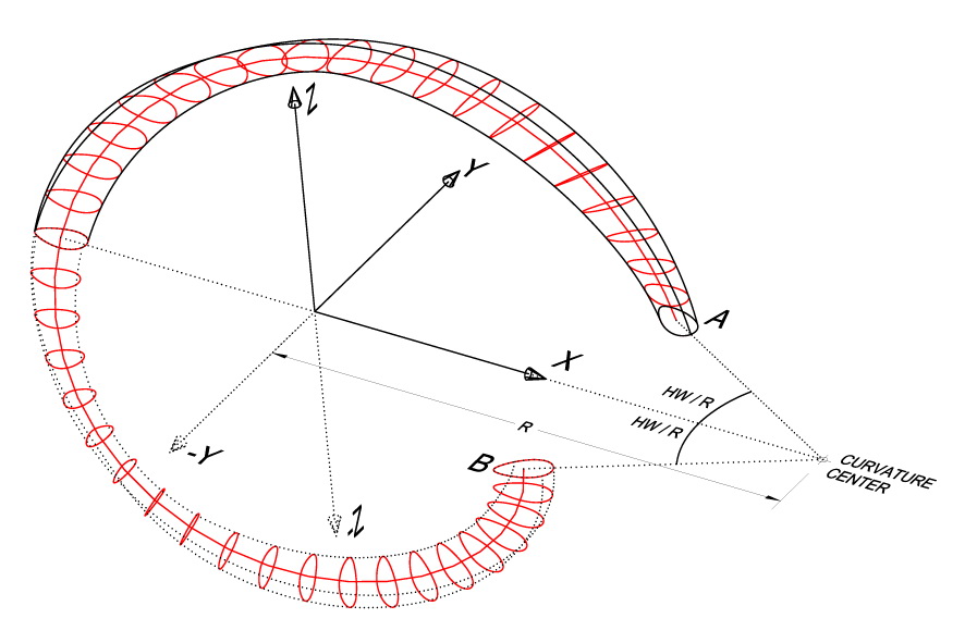
Shape 7
The overground (continuous line) and the underground (dotted line) version of an egged-cross-section Arc-construction, the latter deriving from the former one by inversing both the Y and Z PCS coordinates. The pair is repeatable, resulting in a Helix-construction having multiple turns, if repeated by a 2×HW/R radians angular step. Surface continuity between the overground and the underground parts of the Helix-construction requires that “cross-section” A coincides with “cross section” B if rotated counter-clockwise by the angular step around the curvature center.
Values
The final form of the Arc-construction was defined by the following parameters:
Path parameters
Path Length (Xmax) : 18m
Path Height (Zmax) : 7m
Helix Width (HW) : 10m
Inclination (INC) : 0.7
Cross-section parameters
Ellipse half-length (cx) : 0.65m (both for the start-point and the end-point “cross-section”)
Ellipse half-width (cy) : 0.3m (both for the start-point and the end-point “cross-section”)
Egg deformation (c) : 0
Start rotation angle : PI/4
End rotation angle : 3×PI/4
The curvature radius (R) was set to 300m
Here is a 3D visualization in still images, as well as a 3D animation combined with live video filmed by Danae.